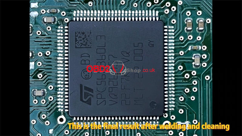
RFA Module CPU SPC560B Blank Chip supports programming JPLA, K8D2, and J9C3 initial data with Yanhua Mini ACDP + Module 24 for 2018+ JLR key adding. Removing the RFA module to replace the SPC56B chip for writing data without soldering. This is a tutorial on how to unsolder the KVM SPC56B chip step by step with Yanhua JLR KVM soldering tool kits.
Part1: Remove SPC56B Chip
Check the full video:
It needs to remove the paint and the chip.
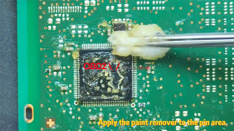
1. Apply paint remover to the top of the chip and the pins, you can see the protective paint start to peel off after 30s. apply the paint remover to the pin area. After about the 90s, you can start cleaning the chip with cotton. Then clean the board with contact cleaner to avoid corrosion of the board paint remover. This is the effect after paint removal and cleaning.
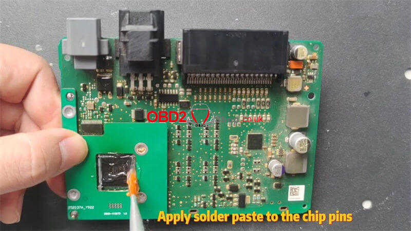
2. Install the chip limit plate, and apply solder paste to the chip pins. Use temperature and airflow adjustable hot air gun to desolder chip. Use a clamp to secure the chip limit plate.
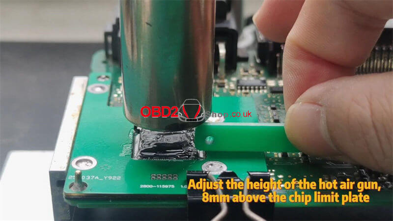
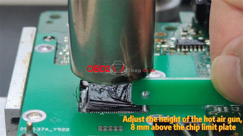
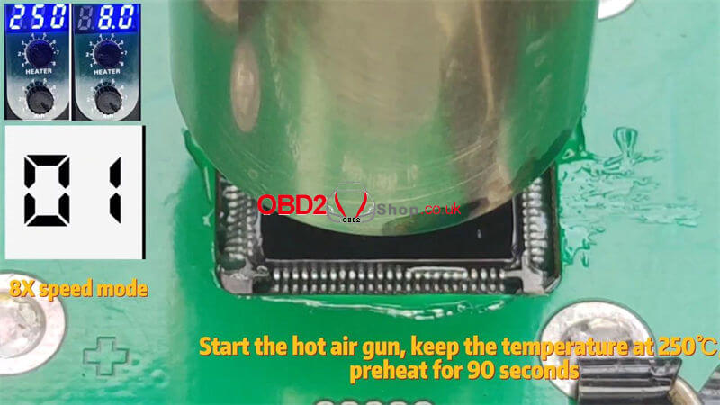
3. Adjust the height of the hot air gun, to 8mm above the chip limit plate. Adjust the air volume to 8 gears. Adjust the preheating temperature to 250℃. Start the hot air gun, keep the temperature at 250℃ preheats for the 90s.
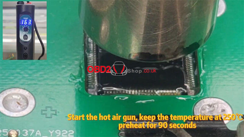
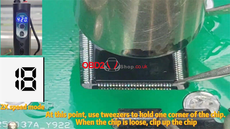
4.After 90s, raise the temperature to 420℃ and heat for 25s. at this point, use tweezers to hold one corner of the chip. When the chip is loose, clip up the chip. About 25s, the chip is loose, remove the air gun and clip up the chip.
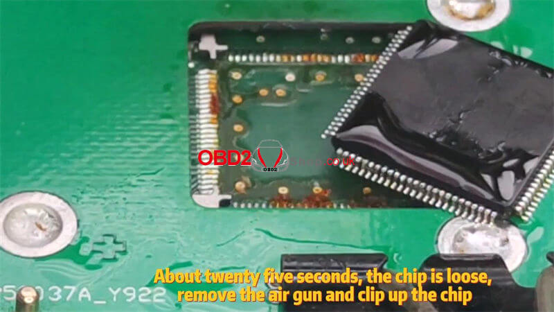
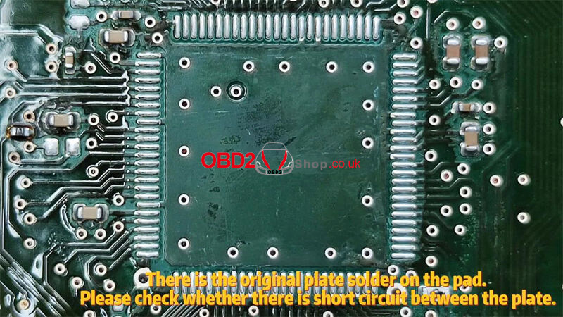
5. Clean the bottom and pins of the chip with paint remover. Then clean the board with contact cleaner to avoid corrosion of the board paint remover. There is the original plate solder on the pad. Please check whether there is a short circuit between the plate.
Part2: Solder SPC56B Chip
Check the full video:
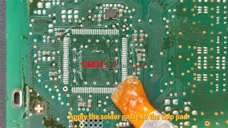
1. Apply the solder paste to the chip pad, and install the chip limit plate. Use clamps to secure the chip limit plate.
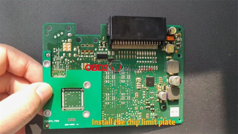
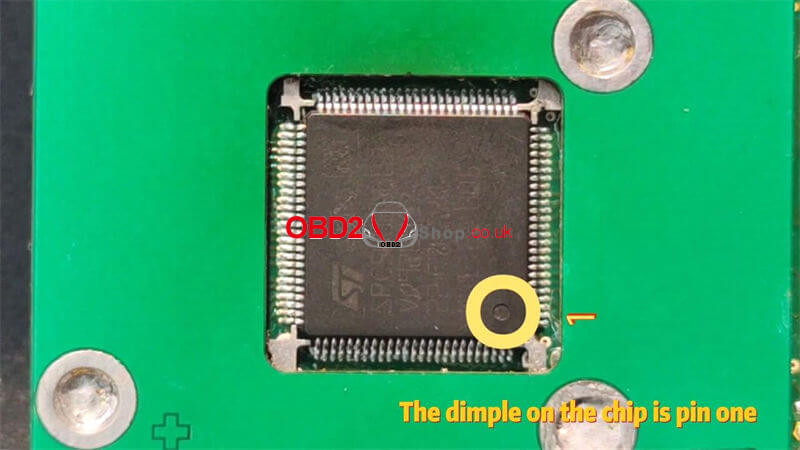
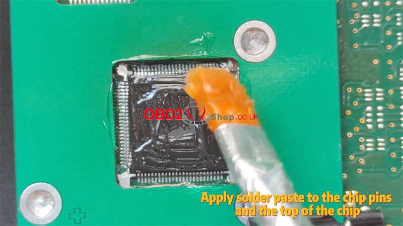
2. Please use Yanhua SPC560B Blank Chip, Yanhua has added solder for the chip pin before delivery. Gently place the chip into the chip limit plate. Please note the chip pin direction. The dimple on the chip is pin1. Apply solder paste to the chip pins and the top of the chip. Check that the chips are placed correctly.
3. Use temperature and air volume adjustable hot air gun to blow and solder chip. Adjust the height of the hot air gun, to 8mm above the chip limit plate. Adjust the air volume to 8 gears, and adjust the preheating temperature to 250℃. Start the hot air gun, and keep the temperature at 250℃ preheats for the 90s.
4. After 90s, raise the temperature to 340℃ and heat for 25s. You can see that the solder on the pin is starting to merge with the solder on the pad. After 25s, please shut down and remove the gun.
5. Use contact cleaner to clean the solder paste on the chip. This is the final result after welding and cleaning.
