
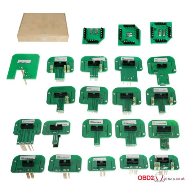
Before going to this topic, let’s have a look at the full set clearly.
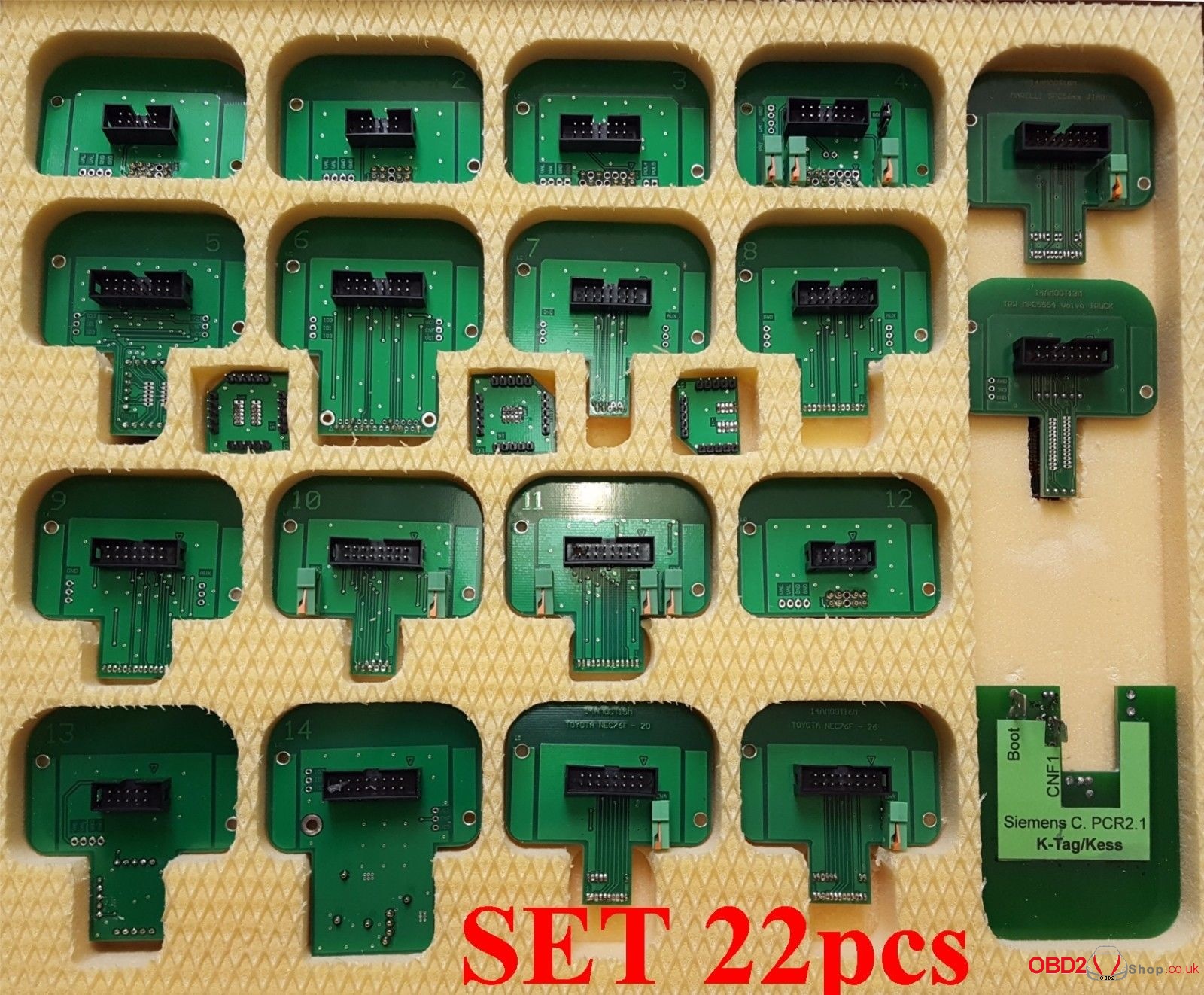
Take out all 22pcs of BDM adapter:
Works on KTAG, KESS,KTM100 and Dimsport Trasdata (Master version and slave version)
Features: Adapter width: ~60mm width for original BDM Probe, not for low quality plastic with 40mm width.
Adapter thickness: 2mm
Read below paragraph on the full set of BDM probe adapters for Denso Marelli Bosch Siemens using tips.
- Open the ECU
- at least one part of the casing (top or bottom) needs to be removed
- refer to other sources (Internet) to get information on which part needs removing on yourECU
- Locate the ECU BDM connector
- usually a set of 10 – 12 pads in two rows (depending on the ECU)
- pads may be 2.54 mm or 1.27 mm apart (depending on the ECU)
- rows may be 2.54 mm or 5.08 mm apart (depending on the ECU)
- if the ECU BDM connector can not be located, chances are that the BDM pads are scatteredall over the ECU PCB in which case you can not use the adapter directly – nevertheless it is possible to manually route the adapter BDM signals to the ECU BDM pads (only for advanced users)
- Locate the ECU BDM pin 1 position
- pin 1 is usually not clearly marked on the ECU BDM pin out
- on an ECU with the standard Motorola BDM pin out pins 3 and 5 are connected to ground -this can be checked either visually or using a multimeter tool
- refer to other sources (Internet) to get more information on the pin 1 position for your ECU
- Place the desired adapter in the frame saddle
- make sure the pogo pins are facing out
- lift the saddle so that the ECU can be slided under the frame adapter saddle
- Place the ECU on the frame
- inspect the adapter for pogo pin 1 location which is clearly marked
- rotate the ECU on the frame so that the adapter pogo pin 1 and ECU BDM pin 1 match
- make sure ECU is firmly sitting on the frame
- double check the ECU position
- Connect the multiplexer board and adapter
- at this point multiplexer board should be connected to the adapter via MUX connector
- this will allow LEDs on the adapter to illuminate the area of interest (where the pogo pinsneed to touch the ECU BDM pads)
- do not connect the tool yet
- Connect the external power (+12 V) to the multiplexer
- multiplexer external power is used to power the LEDs on the adapter allowing easierpositioning of the adapter pogo pins on the ECU BDM pads
- red LED on multiplexer board will light up when external power (+12 V) is present
- at this point the white LEDs on the adapter should also light up
- do not connect the tool yet
- Fine tune the ECU position
- lower the frame adapter saddle to almost touch the ECU BDM pads
- each adapter pogo pin needs to sit on a separate ECU BDM pad
- if pogo pins do not sit on the pads you may be using the wrong adapter – do not use theadapter in this case!
- Lower the frame adapter saddle
- each adapter pogo pin should sit on one ECU BDM pad
- minimum down force should be applied when making the interconnection between theadapter and ECU
- Double check the adapter pogo pin and ECU BDM pad interconnection
- in order not to damage the ECU and/or tool make sure that the steps above have beenperformed correctly
- Connect the tool to the multiplexer board
- only connect one tool at any given moment to the multiplexer
- make sure to use the correct 10-pin IDC connector (FGTECH, XPROG, BDM100&KTAG)for interfacing the tool used:
○ use provided 10-pin to 10-pin cable with FGTECH or BDM100 tools
○ use provided 10-pin to 16-pin cable with XPROG tool
○ use manufacturer 10-pin to 25-pin cable with KTAG tool
- do not connect the tool to the 10-pin IDC connector labeled MUX
- do not power up the tool yet
- For Bosch adapteronly
- Bosch ECUs need to have ECU power supplied on the pogo pins (2 and 9)
- some tools provide dedicated ECU power (BDM100, KTAG) while others do not(XPROG, FGTECH)
- Bosch adapter can be used in both cases, providing that the jumper is properly placed onthe 3-pin header (found on the adapter)
- place the jumper on the adapter on the 3-pin header to the correct position:
○ place jumper over left and central pins when using XPROG and FGTECH tools – this will use +12 V power delivered from the multiplexer board (external power) for powering the ECU
○ place jumper over right and central pins when using BDM100 or KTAG tools – this will use
+12 V power delivered by the tool for powering the ECU
- For Siemens, Delphi and Marelli adapters only
- Siemens, Delphi and Marelli do not provide ECU power on the pogo pins
- in order to power the ECU +12 V and ground signals needs to be connected to the ECU separately (usually over the ECU interfacing connector)
- in this case ECU power can be taken from multiplexer board connectors J2 (+12 V) and J3 (ground), otherwise provide the +12 V ECU power from additional source
- refer to other sources (Internet) to get more information on the location of the +12 V andground pin location for your ECU
- Connect the tool to the PC (or power up the tool)
- perform software installation as described by the tool manufacturer if not done already
- at this point the multiplexer, adapter and the ECU should be properly interconnected withBDM signals and power lines
○ multiplexer red LED should be lit up
○ adapter white LEDs should be lit up
○ ECU power (+12 V) should be present
- connect the tool to the PC (usually done over USB or serial connection)
- Perform BDM operation(s)
- start up the software package to operate the tool
- perform desired BDM operation(s)Note: The user manual is used for reference; in fact, it depends. Try on your own risk.