I come across a topic for discussing SVCI 2020 2019 2018 technical issues arising from beginners and not only on issues:
– device circuitry (circuits, description of nodes, operation logic, pinout, etc.)
– finalization of iron (drivers kan, kline, power circuits, adapter TAG, etc.)
– technical issues related to the operation of the device itself (the device is not detected, driver conflicts, updating, working with the Internet, etc.)
Why exactly 18.19.20? – the most recent, and similar in iron. 19.20 for iron is generally the same.
For questions related to software functions – please do not disturb and write in neighboring topics.
Let’s collect the Old on iron, problems associated with it, necessary / desirable improvements and basic technical questions in one place.
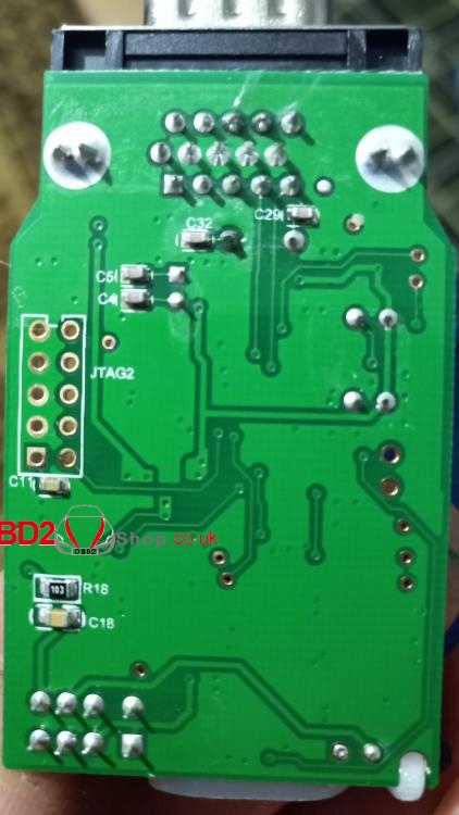
Next, I’ll post a photo of my motherboards from SVCI 2019.
Main board
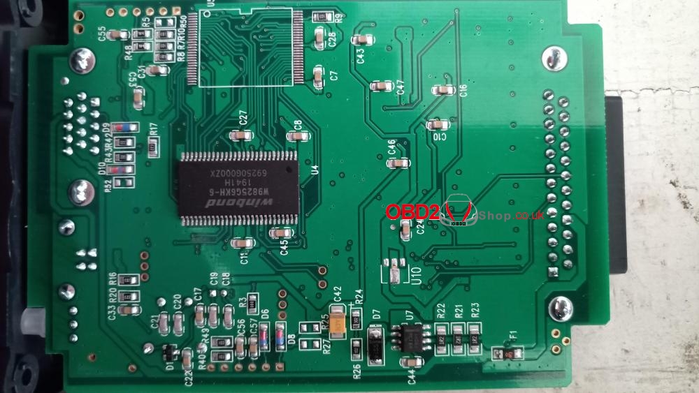
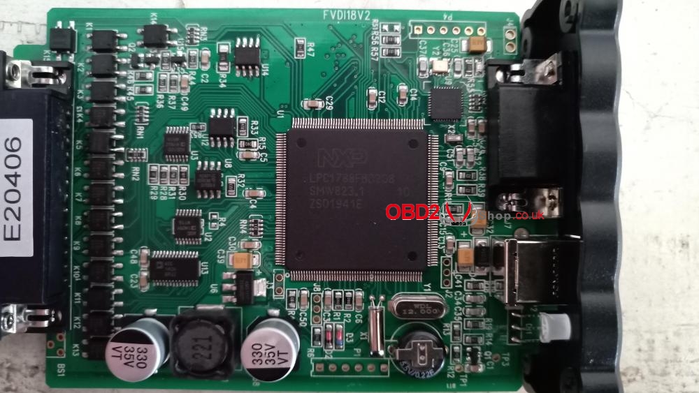
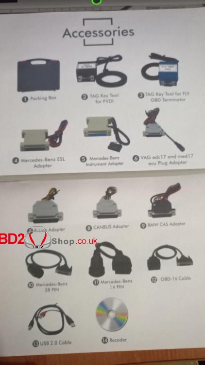
TAG Key tool for FVDI
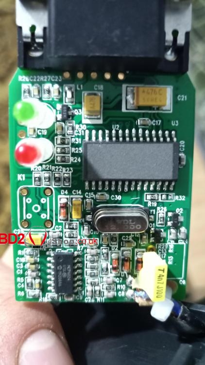
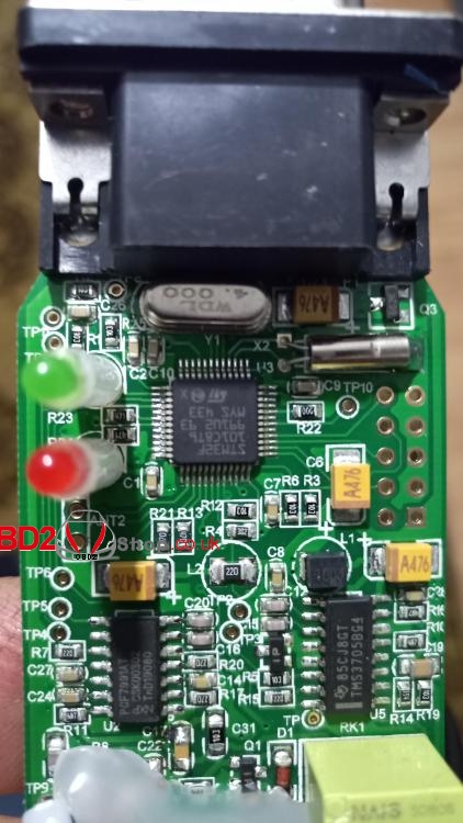
Tag Key tool for Fly OBD terminator
First question is mine
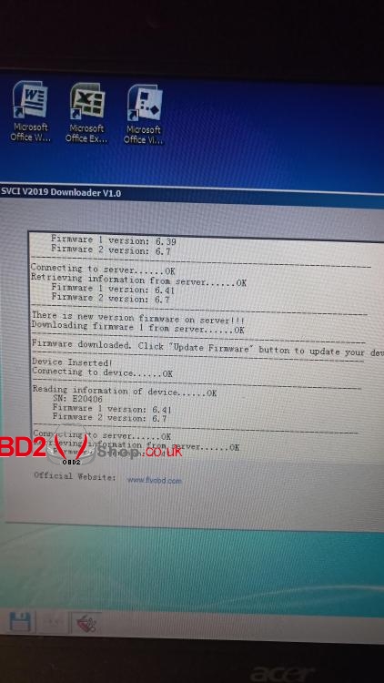
Did anyone update firmware 2019 through the corresponding item at the very bottom of the start window.
He writes that he is connecting to the server, finds the update, downloads and pretends to update.
I’m afraid that the device will fail this update?
And immediately the second:
Two adapters with antennas.
Black: TAG key tool for FVDI
Blue: TAG key tool for FLY OBD Terminator
The diagrams show that blue contains bases on transponders at 125 and 134 frequencies, which is similar to tanga, iprog rfid adapter, carprog, etc. And the same improvements are possible regarding the operation of the antenna and the binding of these pcf7991 and tms3705 drivers for better reading of transponders.
And today, the black 4D chip in the TAG tool didn’t identify or read the black of some device unknown to me . Although 7935 read.
What are two adapters for? Where are they used?
I’ll start to answer a little.
I took a risk: in short, the update went fine, only it was necessary to wait for completion and not to pull the cord ahead of time, blinked a red light and then earned it.
(This is on the 2019 version. HZ as it will be on others. Caution!)
1. The Internet is not afraid. It works when nete is on. At least I started different brands – the norms were loading.
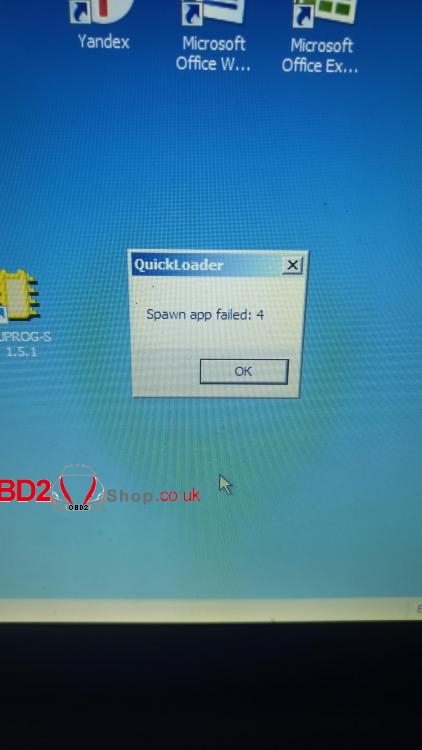
2. There was also a case when brands did not start – wrote something Spawn -4. Although I went into the update – the software saw the device and the firmware version.
At this moment, DrWebCureIt worked, maybe there were not enough resources. He finished work kureit, overloaded the laptop and everything worked as before.
3. The green light on the device is constantly blinking. This is the way to see it – a sign of normal work.
Update!
Today, the message Spawn app failed: 4 again appeared when launching stamps from Loader.
The green LED on the SVCI blinks as usual.
The device sees the update point in the loader: reads the firmware version.
Restarted the laptop – the error is gone. Brands began to run.
Today I checked again: the TAG Key Tool does not read Tiris4CDE.
At 125 frequencies, transponders read.
The weird Tag adapter circuitry – on the mcp6024 – is a 10MHz operational amplifier, rail2rail.
How they made work with transponders based on it – xs
I will sort this out.
Maybe someone has a circuit for the board, adapters, pinout – share.
Two adapters with antennas
black for TAG key
Blue for VVDI2.
At 3/28/2020 at 3:33 PM, saak said:
updated without problems 2019.
Does the TAG Key tool read your 4C, D, E chips?
At 3/28/2020 at 3:33 PM, saak said:
Two adapters with antennas
black for TAG key
Blue for VVDI2.
I’ll learn something already . Thank.
So, played with Tiris chips
4C reads
4D – DOES NOT READ
4E – reads
But, the chips need to be laid directly on the coil perpendicular to the turns
A little to the side – does not read.
In short, the completion of the TAG Key tool adapter is waiting for me
A clearer photo of the TAG Key tool adapter board (black body)
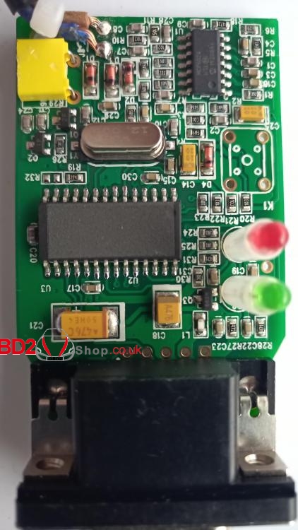
it’s just that simple
But the Vagovskaya reader will be more interesting
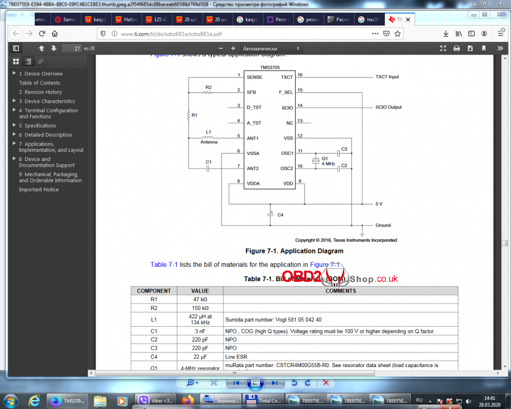
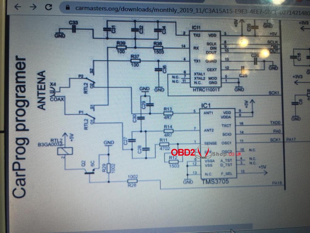
Then we will agree on the names of the tag key tool adapter on the operating system at frequencies of 125 and 134 KHz. There has been approximately the same circuitry since 2014.
It works as a transceiver on the opamp ncp6024 (mine on lm339). The main container is bright yellow (I have gray). The circuit is tuned to 134 kHz. Nearby is a transistor. which, on command from the processor, opens and throws in parallel 0.3 nF. reducing the frequency to 125 kHz. The amplitude of the pulses in the circuit is at least 30 volts. He won’t read otherwise. 14 years old photo attached
blue, for VVDI2 (vag + bmw) – circuit design karprog, ayprog. How it works, chewed on the forum. The only thing that is not visible is how the antenna switches. The relay is not visible in the photo. It is visible only on the back of the board, something similar to a relay.
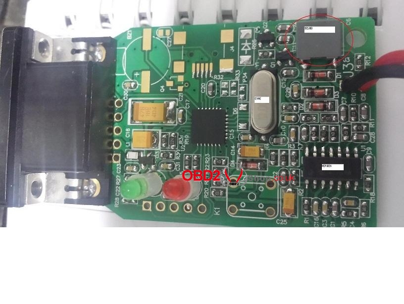
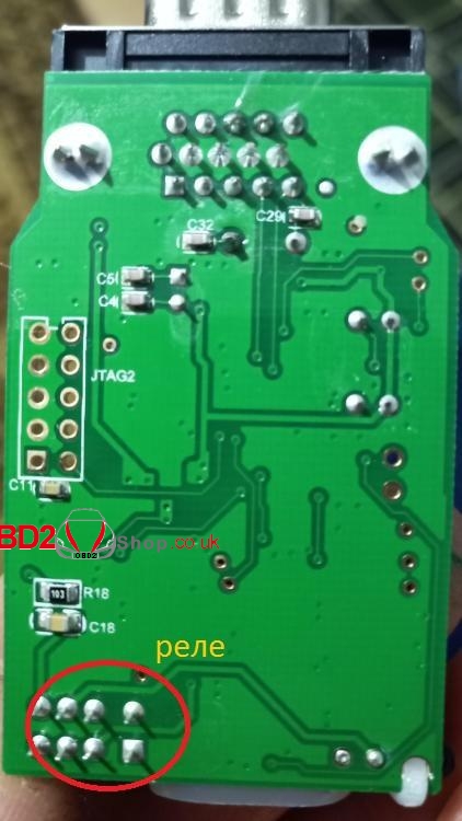
Now for setting up tag kei tool. Do not touch the coil. By selecting the capacity (yellow), we set the circuit to 134 kHz. You can even drop out small condors nearby so as not to interfere. We achieve reading tiris 4d. Then we short-circuit the emitter with the collector of the transistor and select small capacitances, we achieve work at 125 KHz. To read 7936. More precisely, 7946 (key cards). We remove the nozzle from the transistor and check again. If the reading deteriorates, we change the transistor to another …
With this setting, the adapter reads all types of transponders. If you want to work as “from a cannon”, Change the coil to the Opelyovskaya or Reno, toyotovskaya and select .. select containers. But you have to decide which type is needed 134 KHz or 125.
The main thing is to understand that the universal cannot be good .. Especially for narrow-eyed …
It is possible, however, to reduce the quality factor of the circuit with resistors by about 10 approximately. But this is for gourmets …
Do not drive the unverified Old about transistors that close some capacitors.
Here I sketched part of the circuit from the board.
Both transistors are the driver output stage. They pump up the circuit. They are controlled from a microcontroller. The pump frequency is set by the controller.
(try, close the emitter with the collector, it is better on the lower shoulder of the driver, let’s see what happens)
The L1C6 circuit itself is the same at both pump frequencies.
So you need to adjust the L1C6 circuit to resonance to the middle (125 + 134) / 2, so that the pump range is acceptable at both frequencies.
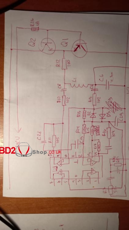
But in general – it is clear. Select a capacitor or coil by monitoring the signal with an oscilloscope while reading transponders 125 and 134 (e.g. 7936 and 4D).
Simply think capacity.
This is for the black Tag Key Tool adapter.
Until blue, until his hands reached.
They both work at both frequencies of 125 and 134 kHz.
Today I double-checked all the chips. Everything except pcf7935 reads, writes, cooks on standard parts.
Just a place on the reel you need to look for.
Press some on the center, some on the inner edge of the coil, put some on the coil from above perpendicular to the direction of the turns of the coil.
Id48, 7936, temic, 4d – reads, writes, cooks. I checked this in the Tag Key Tool.
If C6 is 4300 pF (out of the box it costs 4700), then the voltage on the circuit rises pleasantly, but … the chips stop reading and writing
In short, I’ll leave it as it is, just try to reel a new coil and play with it.
This can be seen from the fact that you are using this black adapter not specialized chips like pcf7991, tms3705, but a microcontroller with firmware and an opamp with a binding.
Yes, and one circuit for two frequencies
Just by increasing the pump by selecting a conder in the circuit for resonance, it is better to not do it, but on the contrary it gets worse.
Well, this is on my version of svci2019.
In earlier versions, I read such a refinement improved sensitivity.
I need to discuss one scheme. I copied the adapter from Chinese abbreviation svci2019 with the Tag Key Tool.
I am interested in breaking a circuit into logical blocks. Where is the receiving part, where is the transmitting part. Where for 125 frequencies, where for 134.
At 125 frequencies, modulation is like AM, at 134 like FM.
In short, where which parts of the circuit are responsible for.
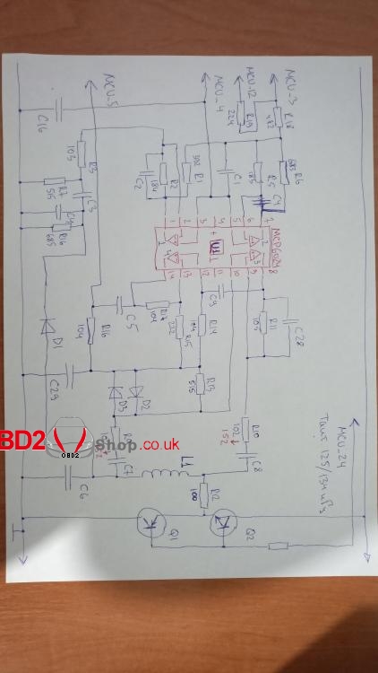
This is the circuit itself and the operational amplifier with strapping. Maybe he missed some element, but not the point.
Well, the D1 diode is clearly a detector of the AM component of the signal in the L1C6 circuit. After it is a filter, an isolation capacitor C3 (after which remains the variable component of the AM signal from the circuit) and the amplifier of the received signal at the op-amp U1_1.
But what is fenced off on the elements D2D3, U1_3, U1_4?
Etc.
As a result, there should be chains:
– reading the signal from the transponder at frequencies 125/134
– signal transmission to the transponder at frequencies 125/134
Tinkered during the weekend with this black TagKeyTool adapter.
I tried increasing / decreasing the value of the capacitor to wind a coil for it, reading / writing different transponders.
Found out: that the best work is on the factory rating of the capacitor C6 4700pf. But if you reel another coil, the sensitivity can be increased.
Better sensitivity on a smaller diameter coil (35mm). With increasing diameter, the sensitivity decreases – even if you manually select the turns while reading / writing transponders.
I made a connector on the wire to which I will connect different individually configured coils.
The technique is this: we count the coil at a frequency of 125 kHz for a given 4700pf loop conder. We get the inductance. Next, according to the required inductance, we calculate the winding data of the coil: the approximate number of turns on our diameter and winding width (1 cm).
And then, while reading / writing a test transponder, it is better for pcf7936 to play with turns, achieving the best reading and writing (it is necessary to write, because it happens that it reads normally but does not write).
Plus or minus a couple of turns turned out to be of great importance!
The total inductance on my coil is 365 μH.
All.
Frequency 134 will have to work on this coil. It is possible to make plus or minus 1-2-3 turns of reading-writing already at 134 frequency.
I used the transponder emulator from Xhorse so as not to screw up individual chips. The emulator can always be retrained.
Yes. Still. 134 frequency is terribly afraid, as it turned out, of pulse pickups. A PSU from a laptop or an included soldering station near the coil leads to errors or complete inoperability at 134 frequencies.
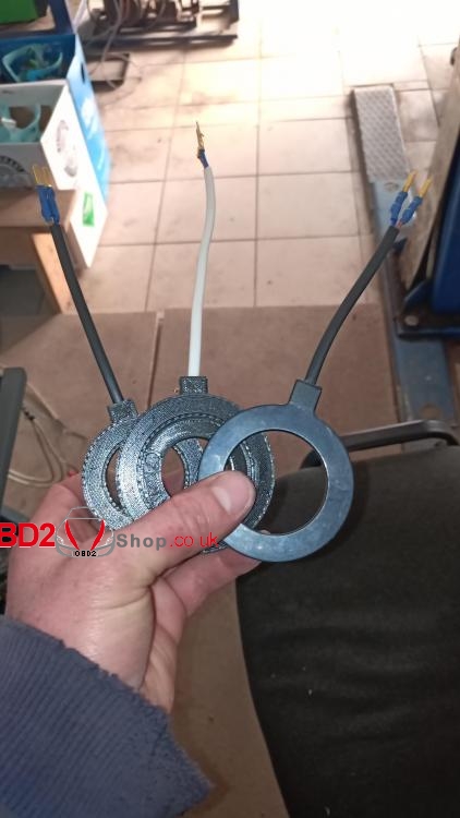
Once again I checked the operation of this adapter on a larger coil inductance. C6 took 2200pf. I wound a coil for it under 125 kHz.
Pumping has grown markedly. But reading / writing did not get any better. Errors at 125 frequency were thrown.
134 refused at all.
In short, everything. I tie with this tag key tool adapter. It is assembled on non-specialized microcircuits such as pcf7991, tms3507, and on the microcontroller and the opamp, and it is already incorrectly processed by these nodes to see the change in pump and signal from the coil.
Shorter than C6 4700pf. 35mm reel. Inductance 365mkg. + – a turn-two is already in the process of reading and writing chips.
Yes. The l9637d k-line driver was replaced by its faster analogue l9613 according to the recommendations of people from neighboring branches on FVDI.
To be upgrading…
